How CCTV CAD Tools Simplify Security System Design
Designing a CCTV system from scratch is rarely as straightforward as picking cameras and mounting them on walls. Every site has its own geometry, lighting conditions, and blind spots. Over the years I have worked on enough installations to know that a sketch on a napkin never survives contact with a real ceiling grid. That is where a proper design tool becomes indispensable. Some of the most effective planning workflows now rely on CCTV CAD capabilities to turn rough ideas into measured, client-ready layouts.
Why precise layout matters before you run a single cable
I once watched a team install eight IP cameras in a warehouse only to discover that the lens focal length they had chosen left every aisle with a dead zone wide enough to hide a forklift. The mistake was not in the hardware. It was in the planning. They had never mapped the coverage area against the actual floor plan. Had they used a digital design environment, they could have placed virtual cameras on the blueprint, adjusted the field of view for each lens, and checked the overlap before anyone climbed a ladder.
Camera placement is the single most consequential decision in any security system. Get it right and you cover the space efficiently with fewer units. Get it wrong and you end up adding extra cameras, running longer cable runs, and straining your PoE switch budget. A design tool that incorporates CCTV CAD lets you test placement scenarios without touching a single tool. You can move a camera two feet to the left and instantly see how that shift changes the coverage area. That kind of feedback loop is impossible with paper and pencil.
Bridging the gap between site survey and installation
A thorough site survey gives you measurements, lighting notes, and existing infrastructure details. But translating those notes into a coherent plan takes more than memory. When I first started designing systems, I would sketch everything by hand, then try to convert those sketches into a bill of materials. I inevitably missed conduit bends or underestimated cable run lengths. The result was either a return trip to the supply house or an ugly surface-mount raceway that the client hated.
Modern design tools let you import or trace floor plans and then lay out the entire system in one environment. You can assign resolution targets per zone, specify night vision requirements for dark corridors, and decide where motion detection should trigger recording. Because the tool knows the camera specs, it can warn you if a given lens focal length will produce too narrow a field of view for the space. That kind of feedback is gold during the planning phase.
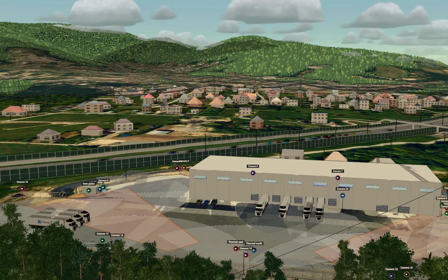
Using CCTV CAD inside a design tool also makes it easier to communicate with the client. Instead of handing them a list of part numbers, you can show a plan view with every camera icon positioned exactly where it will go. The client sees the coverage area shaded on their own floor plan. They understand why that one IP camera in the corner covers the loading dock while the analogue camera in the hallway covers the entry. That visual clarity builds trust and reduces the number of change orders later.
Hardware decisions that flow from the layout
Once the camera placements are locked, the rest of the system starts to define itself. You know how many cameras you need and where they live, so you can calculate the total bandwidth and storage requirements. That tells you whether an NVR with H.265 compression is sufficient or if you need to step up to a more capable video management system. You also know the distance from each camera to the nearest PoE switch. If a cable run exceeds the 100-metre limit for Ethernet, you can plan for a midspan switch or switch to a different camera location.
The same logic applies to legacy systems. If you are working with analogue cameras, you will route coax to a DVR and factor in power over the same cable. A good design tool handles both IP camera and analogue camera workflows, because real-world projects often mix technologies. I have done retrofits where the client wanted to keep existing coax runs for a few analogue cameras while adding new IP cameras on a separate network. Tracking that hybrid system on a single layout prevented me from accidentally doubling up on cable runs or mismatching recorder inputs.
ONVIF compatibility is another detail that becomes obvious when you see the whole system in one view. If a camera and the NVR both support ONVIF, you can confirm that before you order. If not, you either pick a different camera or budget for a driver. Catching that incompatibility in the design phase saves a lot of frustrated phone calls during commissioning.
From layout to client proposal and bill of materials
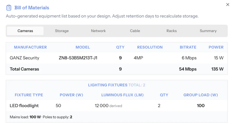
One of the most tedious parts of system design used to be generating the proposal. After you finalise the layout, you have to list every camera, bracket, cable, connector, and switch. Miss one item and the installation stalls. A design tool that includes CCTV CAD functionality often auto-generates a bill of materials from the items placed on the plan. You can review it, adjust quantities, and produce a clean client proposal without re-entering data.

I remember a job where the client wanted three options at different price points. Doing that manually meant three separate spreadsheets and three sets of sketches. With a digital design tool, I duplicated the layout, swapped camera models to change resolution and night vision capability, and the tool recalculated the coverage area and the bill of materials automatically. The client could compare the options side by side and make an informed decision. That process used to take me a full day. Now it takes a couple of hours.
The proposal itself benefits from the same visual approach. You can include a rendered plan view, a summary of coverage area per zone, and a breakdown of equipment. The client does not need to understand NVR channel counts or PoE budgets. They see a clear picture of what they are getting and why it solves their security concerns.
Practical tips for getting the most out of a design tool
Based on my own experience, here are a few habits that make a real difference when you are using a CCTV CAD approach:
- Start with an accurate floor plan. Even a rough sketch scaled to the correct dimensions is better than guessing. If the site survey included laser measurements, use them.
- Place cameras in priority order. Cover critical zones first, then fill in secondary areas. This keeps you from over-engineering low-risk spaces.
- Check the field of view for every camera. Do not assume a standard lens will work. Adjust the lens focal length in the tool and see what changes.
- Run the cable paths mentally before you commit. A camera mounted perfectly on paper may have no practical path for the cable run. The design tool should let you sketch rough conduit routes.
- Review the bill of materials against the plan. Make sure every camera, mount, and power source is accounted for before you send the proposal.
Choosing between IP and analogue in the same layout
Not every installation needs a full IP camera system. Sometimes the budget or the existing infrastructure points toward analogue cameras. A good design tool should not force you into one technology. I have used CCTV CAD workflows to design mixed systems where the core perimeter uses IP cameras with high resolution and analytics, while interior corridors use cost-effective analogue cameras for general awareness. The tool handles both because it treats each camera as an object with its own specs: resolution, lens, night vision capability, and recording destination.
The key is that the layout drives the decision, not the other way around. You place a camera because the coverage area demands it. Then you choose the technology that fits the requirements and the budget. That workflow keeps the design honest and prevents you from overspending on features the site does not need.
Final thoughts on design discipline
Good CCTV design is about reducing uncertainty before you commit to hardware. A design tool that supports CCTV CAD gives you a controlled environment to test assumptions, spot conflicts, and document your reasoning. The result is a system that installs faster, costs closer to the estimate, and actually covers the areas the client expects.
I still carry a tape measure and a notebook on every site survey. But by the time I sit down to plan the system, I want a digital workspace where I can move cameras, check fields of view, and generate a client proposal without redoing the math every time. That is what a purpose-built design tool provides. And once you get used to planning that way, you will wonder how you ever worked without it.